Section 1: Classification of CNG Refueling Sub-stations
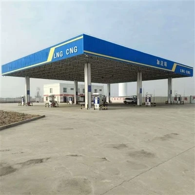
CNG refueling stations are primarily categorized into three types: mother stations, standard stations, and sub-stations. Mother stations typically draw gas from high-pressure pipelines; they refuel CNG tube trailers (gas cylinder trucks), are responsible for transporting gas to sub-stations, and also directly refuel individual CNG vehicles. Standard stations primarily draw gas from urban medium-pressure pipeline networks to directly refuel CNG vehicles. Sub-stations, on the other hand, utilize CNG tube trailers as their gas source and are dedicated exclusively to refueling CNG vehicles. It is worth noting that, because standard stations draw gas directly from the natural gas pipeline network-often involving high flow rates-they may exert a significant load on the urban gas grid. This could potentially disrupt gas supplies to residential and industrial users; therefore, the selection of a site for a standard station requires comprehensive and careful consideration. Currently, the "mother-sub" station model is the most prevalent configuration, within which sub-stations are further classified into two types: conventional sub-stations and hydraulic sub-stations. In the following sections, we will delve deeper into the technical details and characteristics of conventional refueling sub-stations.
Detailed Analysis of Conventional CNG Refueling Sub-stations
We will now focus specifically on conventional CNG refueling sub-stations, exploring in depth their operational principles and key features.
Hydraulic CNG Refueling Sub-stations
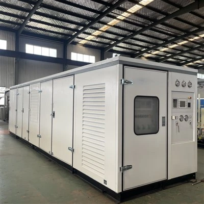
The technology behind conventional CNG refueling sub-stations relies primarily on traditional gas compressor-based boosting systems. These types of sub-stations are typically constructed in locations where there are no existing natural gas pipelines in the immediate vicinity. They are frequently sited within urban areas to provide convenient refueling services for vehicles, or in rural industrial zones and other regions lacking laid gas pipelines, where they serve as a source of natural gas energy supply. At the mother station, natural gas is compressed and stored; subsequently, compressed natural gas-pressurized to 25 MPa-is transported to the sub-station via specialized transport vehicles (tube trailers). The sub-station then proceeds to refuel individual CNG vehicles. For sub-stations located in industrial zones, the operational process is as follows: Low-pressure or medium-pressure natural gas is boosted by compressors to a pressure range of 20–25 MPa. It is then compressed into specialized steel cylinders or tube bundles, which are mounted onto skid-based trailer units equipped with towing mechanisms. These vehicles transport the natural gas to the sub-station, where they connect to a gas-unloading system and CNG pressure-regulating equipment to facilitate the transfer of gas. After passing through a pressure-reducing skid to lower the high-pressure natural gas to the user-specified range of 0.2–0.4 MPa, the gas enters the distribution pipeline network and becomes available for user consumption.
The architectural diagram for a conventional CNG daughter station is shown below:
Architecture and Process of a Conventional CNG Daughter Station
The process flow for a conventional CNG daughter station operates as follows: When a CNG trailer arrives at the station, it connects to a gas unloading column via a high-pressure unloading hose. Two distinct lines are utilized here: the first is a "direct supply" line, which leverages the inherent pressure within the trailer's cylinders to directly refuel vehicles. This line utilizes the station's on-site gas storage cylinder banks-comprising low-, medium-, and high-pressure banks-to replenish a vehicle's fuel tank up to a pressure of 20 MPa. When the pressure within the storage cylinder banks drops below 20 MPa, the second-or "pressurization"-line activates; the compressor begins operation, drawing natural gas from the trailer's cylinders to restore the pressure in the storage banks back to 20 MPa.
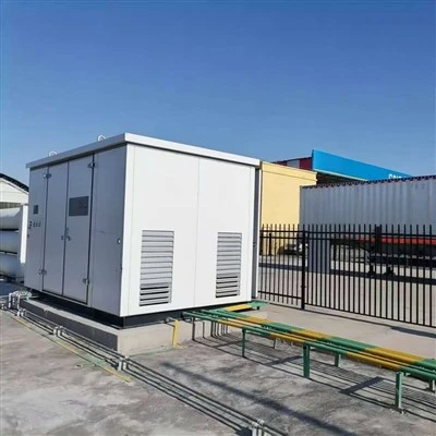
Key equipment at a conventional CNG daughter station includes the skid-mounted gas compressor unit and its boosting system, the gas storage cylinder banks (with a total capacity of 8 m³), the gas dispensers (which utilize "three-line" refueling technology), the gas unloading column, as well as safety and security systems and power distribution equipment (such as compact substation transformers).
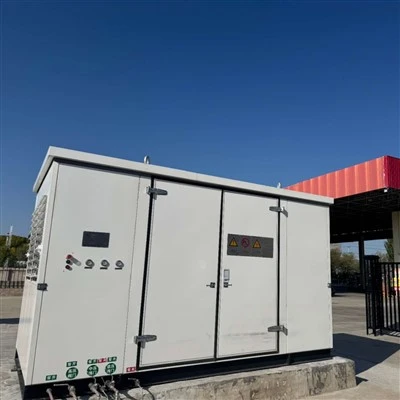
Next, we will examine the technical characteristics and architecture of a hydraulic CNG daughter station. Hydraulic daughter stations are typically constructed in locations-often within urban areas-where no existing natural gas pipeline infrastructure is available in the vicinity of the refueling station, thereby enabling them to provide refueling services to vehicles. This type of station employs a hydraulic boosting system to replace the traditional gas compressor-based boosting system. It features a high degree of system integration, robust refueling capacity, ease of installation, and low operating costs. Its architectural diagram is shown below:
Architecture and Process of a Hydraulic CNG Daughter Station
The process flow for a hydraulic CNG daughter station is as follows: Upon the arrival of the CNG trailer at the station, quick-connect couplings are used to link the high-pressure fluid supply hose, high-pressure fluid return hose, control gas bundle, and high-pressure CNG outlet hose to the hydraulic daughter station's skid unit. Once the system is ready, the high-pressure hydraulic pump begins operation. The PLC automatic control system opens the liquid inlet valve and gas outlet valve of the first storage cylinder while simultaneously closing its liquid return valve. This injects a high-pressure liquid medium-specifically, a low-volatility hydraulic oil-into the storage cylinder to maintain the gas pressure within the cylinder truck's storage vessels between 20 and 22 MPa. The CNG flows from the storage cylinder's gas outlet, through a high-pressure CNG hose, and into the buffer tank located on the hydraulic sub-station skid. It is then conveyed via high-pressure piping to the CNG dispenser to refuel CNG-powered vehicles. When approximately 95% of the natural gas has been discharged, the automatic control system issues a command to close the liquid inlet and gas outlet valves of that specific storage cylinder, while simultaneously opening its liquid return valve. This allows the high-pressure liquid medium within the cylinder to flow back into the storage tank located on the skid, driven by the combined forces of residual gas pressure and gravity. Subsequently, the liquid inlet and gas outlet valves of the second storage cylinder open, and the high-pressure liquid begins to fill it. This process continues until the majority of the liquid medium from the first storage cylinder has returned to the storage tank. Throughout this operation, the PLC program control system ensures that the eight storage cylinders operate in a sequential rotation, while pneumatic actuators open and close the inlet and outlet valves of each cylinder precisely as dictated by the PLC control program. Once a cylinder truck has finished discharging its gas, personnel need only switch the quick-connect coupling to the next cylinder truck-a transfer process taking approximately 3 to 5 minutes-to ensure the uninterrupted operation of the refueling station.
Key equipment components of the hydraulic refueling sub-station include the hydraulic sub-station skid assembly (comprising the skid structure, booster system, etc.), the control cabinet, instrument air supply equipment, the CNG dispenser (utilizing single-line refueling technology), the safety and security system, and power transformation and distribution equipment (such as box-type transformers). In the following section, we will delve deeper into the methodology for selecting equipment for CNG refueling sub-stations.
Currently, CNG vehicle refueling stations primarily serve municipal buses and taxis. Consequently, both their market prospects and gas supply capacity are constrained by urban planning regulations, resulting in certain inherent limitations. Although conventional daughter stations and hydraulic daughter stations ultimately deliver the same product-yielding identical revenue-differences in their process equipment result in variations in initial engineering costs and operational expenses.
Equipment Selection for CNG Daughter Stations
This constitutes a critical phase in identifying a technically sound and economically viable solution. It not only influences project cost control but is also vital for minimizing operational expenses. Over the entire lifecycle of a project, total costs are a composite of the initial engineering cost and the operational costs incurred during the service period. Therefore, when evaluating and comparing alternative engineering designs, one must not focus solely on the engineering costs incurred during the construction phase, but also give full consideration to the long-term operational expenses during the service phase.
A comprehensive analysis serves as the foundation for equipment selection; its objective is to efficiently allocate and utilize resources and capital to maximize investment returns. During the selection process, various methodologies can be employed to compare benefits against costs, ranging from comprehensive comparisons to partial comparisons. Regardless of the specific method adopted, it is imperative to adhere to the principle of consistency in the calculation parameters for both benefits and costs, thereby ensuring the comparability of the various proposed solutions.
Commonly utilized methods for comparative selection include the Benefit Comparison Method, the Cost Comparison Method, and the Minimum Price Method. Among these, the *Internal Rate of Return on Incremental Investment*-a specific technique within the Benefit Comparison Method-is particularly insightful. By calculating the financial Internal Rate of Return (IRR) on the incremental investment between alternative solutions and comparing it against a predetermined benchmark rate, this method provides a clear and intuitive reflection of the economic performance disparities among the various options. In a market economy environment, where profit maximization is the inherent nature of capital, this method proves to be of paramount importance during the comparative evaluation of project proposals.
Overview of Core Equipment for Conventional Daughter Stations
In the construction of CNG daughter stations, conventional daughter stations play an indispensable role, largely defined by their specific array of key equipment. These core components are not only critical for controlling project costs but also directly influence the optimization of operational expenses. Consequently, when evaluating and comparing alternative design proposals, a comprehensive assessment of this equipment becomes a pivotal step in identifying a technically sound and economically rational solution.
Overview of Core Equipment for Hydraulic Daughter Stations
In the construction of CNG daughter stations, hydraulic daughter stations play a pivotal role, distinguished by their unique set of specialized equipment. These core components are not only essential for controlling project investment costs but also have a direct impact on enhancing operational efficiency. During the process of evaluating and comparing alternative proposals, an in-depth analysis of this equipment constitutes a critical step in identifying the optimal technical and economic solution.